As promised, here is a brief description of the N-mod and N-club modular systems. This is what I posted on the blog a while back, and I need to expand it a bit more……
N-mod
The ESNG works to two N-gauge modular systems. With our show coming up, perhaps a quick reminder of the standards is in order. The first is N-mod. This is an adaptation of the USA N-Track system, the main difference being that there are 4 tracks and all tracks are at the front of the board.
The length of the module is defined as 4 foot, to keep a standard geometry and enable a continuous layout, but the width can vary, behind the four tracks, as desired. All track is PECO Code 80 (at least at the module ends.) The modules are joined by a short, nominally 3 inch, removable length of track to take up variations in length and width. And variations there are, perhaps due to unevenness in the hall floor, wood changing shape with time, and the general incompetence of the members.
The sketch shows these dimensions.

Here are our ‘official’ module specifications…
Standard Module dimensions are:
- Length is 4ft / 1220 mm), with the more adventurous using any multiple modules of 4ft to construct larger layouts.
- Depth, front to back of the module, including club tracks, can be between 1ft/304mm and 2ft 6in / 760mm. Some members integrate the club tracks into their module design, others attach a simple 6″ extension unit to the front of their layout to carry the club Tracks across it for group meetings.
- Height of Track base from floor (at track joint) is 3ft / 915mm
- Module front and sides, excluding baseboard, should be 3in / 76mm in height, to facilitate clamping of the module to its’ neighbours when in a circuit
Each module makes provision to carry four (4) Club Tracks, named, from module viewing or front edge Tracks 1,2,4 & 3. (This numbering is a consequence of the club converting from having 3 to 4 club running tracks and not wishing to embark on a module rewiring programme.) These tracks are controlled from the “fiddle yard” when the module is in use in a Club circuit. During operation Track running directions are decided by the Fiddle Yard operators. However most operators follow a running convention based on British railways: namely Track 1, the track closest to the viewing edge, runs clockwise and Track 3, the track furthest from the viewing edge, runs anti-clockwise, with Tracks 2 & 4 running in either direction.
Only standard Code 80 Track, or equivalent, should be used for club tracks. To protect track ends in transit, Club Tracks stop 1.5″ from the ends of the module, and a short length (3″) of track is inserted across the join, and held in place with rail joiners, when a layout is assembled. Rails must stop 1.5in / 38mm from the edge of the module. Track centres are to be positioned, as measured from the front of the module, as follows : Track 1 = 2in / 51mm, Track 2 = 3in / 76mm, Track 4 = 4in / 102mm and Track 3 = 5in / 127mm. Sleepers must be cut back at least 0.25in / 6mm from rail ends.
Any tunnel or bridge over Tracks 1, 2 or 3 must have sufficient clearance for continental stock with overhead pantographs. No turnoffs are allowed on tracks 1, 2 or 4, but are permitted on track 3 with 2-pole isolation.
Electrical interconnection of adjoining modules is by use of standard Plug and Socket connectors, as well as rail joiners. RS 12-pin connectors to be used for interconnection as follows. (See part numbers below)
Pin 1 = Track 1, outside rail; Pin 2’= Track 1, inside rail;
Pin 3 = Track 2, outside rail; Pin 4 = Track 2, inside rail;
Pin 5 = Track 3, outside rail; Pin 6 = Track 3, inside rail;
Pin 7 = Track 4, outside rail; Pin 8 = Track 4, inside rail;
Male connector (with pins) to be fitted at Left hand end of module as viewed from spectator face; Female connector (with sockets) fitted to Right hand end. It is recommended that tracks be wired to a terminal block under the module and leads taken from terminal block to the plug and socket connectors.
RS Connector sets:
12-way Moulded Free Plug: 466-747
12-way Moulded Chassis Socket: 466-775
Tinned brass Pins for use in moulded plug; 466-797
Tinned Sockets for use moulded socket; 466-826
12-way Terminal strips; Plug & socket type; 424-579
N-club
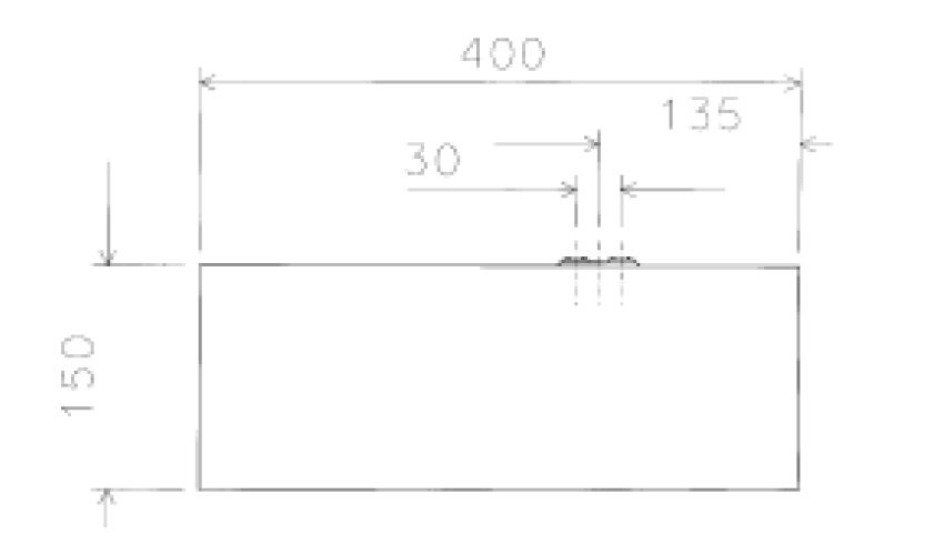
The idea of an N Club International module came from wanting a pan-European N gauge standard. The boards are double tracked (although a single track standard also exists). The standard board width is 400mm, with tracks at 120 and 150mm from one side. The boards can be any length, as the modular layouts set up are generally end-to-end, with loop boards at either end. Common lengths are 800 and 1200mm. Junctions can be used to set up a complex layout.
The track goes right to the end of each board, and is laid with a jig. The modules are aligned by dowels and bolted together. Theoretically, this method of using a precision jig guarantees a perfect alignment between adjacent modules. It usually works! Track is PECO Finescale Code 55 which has a more prototypical look thanks to its lower profile Code 55 rail.
The sketch shows the board end profile.
A while back Duncan produced a good translation from the official N-club documents, and I’ve attached it here…..
ESNG_NCI_Module_Standard_EN_0_95
Comparison….
Two different standards, and two different concepts. N-mod does allow some crowd pleasing running at an exhibition. We keep enough N-mod modules to build a circuit in our meeting room, and allows members to run (and watch) plenty of trains on club nights. NCI perhaps allows more variation of track planning, as double track lines were (and are) more common than four-track sections.
